I did a previous post on my first CNC linear rail upgrade, that was on my Y axis which has two drive motors. That upgrade was so impressive that I decided to next do an upgrade on the X axis, across the gantry. When I first made my machine I used the suggested aluminum angle stock that has a V pressed on the edge of one side by the V bearings used there. The bearings are smooth and the rails are good initially, but they do wear with the weight of the router fixture and the small amount of debris that finds its way into the works there. There are adjustments, but they are also not really easy to do and keep everything perfectly true and square, so I hesitate to make changes there. When the rail gets loose enough that there is noticeable play in the bearings I do make changes.
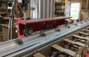
On the red angle brace in the picture you see two bolts with jamb nuts, those are the adjusting bolts, and there are four on each linear axis, one at each of the four bearings. On the other side of the bracket are the v bearings and bolts they ride on. There has to be some flex in this system, and I didn’t see a problem with that in the beginning, but with larger projects and more precision cutting these issues were beginning to be a problem. So the linear rail upgrade was necessary, and I did the same rails on this axis that I used on my Y axis. These are good rails, very smooth and easy to install.
The issue here on this rail is that there has to be an upper and lower rail, unlike the Y where I could only do an upper, this has a twist from the Z axis to correct and hold, so both upper and lower have to be nice and tight. Below is the lower rail, and this is where I see the looseness first when here is some. You may be able to see that the edge of the aluminum rail has a grey area, that is where the V bearing rides and where the wear shows up.
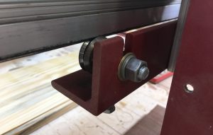
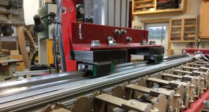
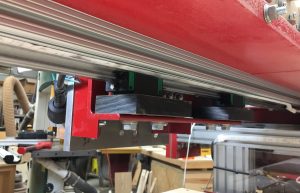
So to service this I have to remove the Z axis and bearings for the X axis along with brackets. The pictures below show the new rails installed and ready to try out.
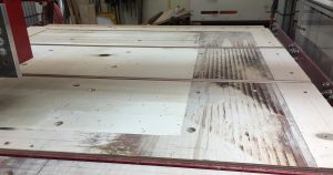
Along with these changes there has to be a re-flattening of the spoil board. I can also tell how well the three axis are squared, I make many measurements along the way to ensure things are right but ultimately the cut shows any minor errors. I am also using a new spoil board bit, one that is smaller and has replaceable carbide cutters. The other cutter I’ve used leaves burn marks even though it is sharp and I use the proper feed and speeds. You can see the difference in the picture below, the inner cut is the new bit, the outer area is the old bit. Looseness in the axis also could contribute to the poor previous cut. The material being cut is Baltic Birch ply wood, which usually cuts nicely and without much burning.
I can say that after replacing the two axis I’ve done so far, the Z axis is next. The last problem I kept having was drilling holes. They were becoming more oval instead of nice round holes, and the play in the Z axis has been identified as the area of concern, so as soon as I have a weekend that doesn’t require machine use, I’ll do the last linear rail system, and those rails are already in my possession and ready to go.
